
Electrical Integrity: Grounding, Charge Stability, and Voltage Optimization
Grounding Deficiencies and Spark Marks in Automatic Electrostatic Powder Coating Systems
When grounding isn't done properly, it leads to stray electrical currents that mess up how the powder gets charged, which often leaves those annoying spark marks right on the finished product's surface. According to recent studies by Ponemon in 2023, roughly a quarter of all coating problems come down to grounding issues, and this costs manufacturing plants around seven hundred forty thousand dollars each year just for fixing what went wrong. What typically goes wrong? Well, there are several common culprits: when the connection between the part and the ground isn't solid enough, when hanging hooks get dirty over time, or when they use ground wires that aren't thick enough for the job. All these things interfere with where electricity should go, making the powder stick unevenly and sometimes creating little sparks in specific spots. If someone measures resistance and finds it going over 1 megohm using their trusty multimeter, that's pretty much confirmation that something's wrong with the grounding system according to Gema's research back in 2022.
Back Ionization and Faraday Cage Effect: How They Reduce Transfer Efficiency
Back ionization happens when too many charged particles build up in areas that are already coated, pushing away new powder particles. At the same time, what's called the Faraday cage effect works to push electrostatic fields away from hollow spaces and inner corners, making most of the coating land on outer surfaces instead. When both of these things happen together, they can cut down how efficiently powder sticks to complicated shapes by somewhere between 40 and 60 percent. Parts with lots of deep pockets or narrow angles tend to suffer the most from this problem during powder coating processes.
Voltage Paradox: Why Higher kV Isn’t Always Better for Electrostatic Powder Coating Systems
Excessive voltage (>100 kV) accelerates powder velocity but intensifies back ionization, ozone generation, and dielectric breakdown risk. Optimal kV settings depend on powder chemistry and part geometry—not blanket maximization:
| Material | Recommended kV Range | Efficiency Loss Beyond Threshold |
|---|---|---|
| Epoxy Resins | 60–80 kV | 25% |
| Polyester Hybrids | 70–90 kV | 30% |
Balancing voltage with gun-to-part distance (150–300 mm) and airflow (0.5–1.5 bar) ensures stable particle penetration without field distortion. For high-detail components, reducing kV below 50 kV improves cavity coverage while minimizing repulsion.
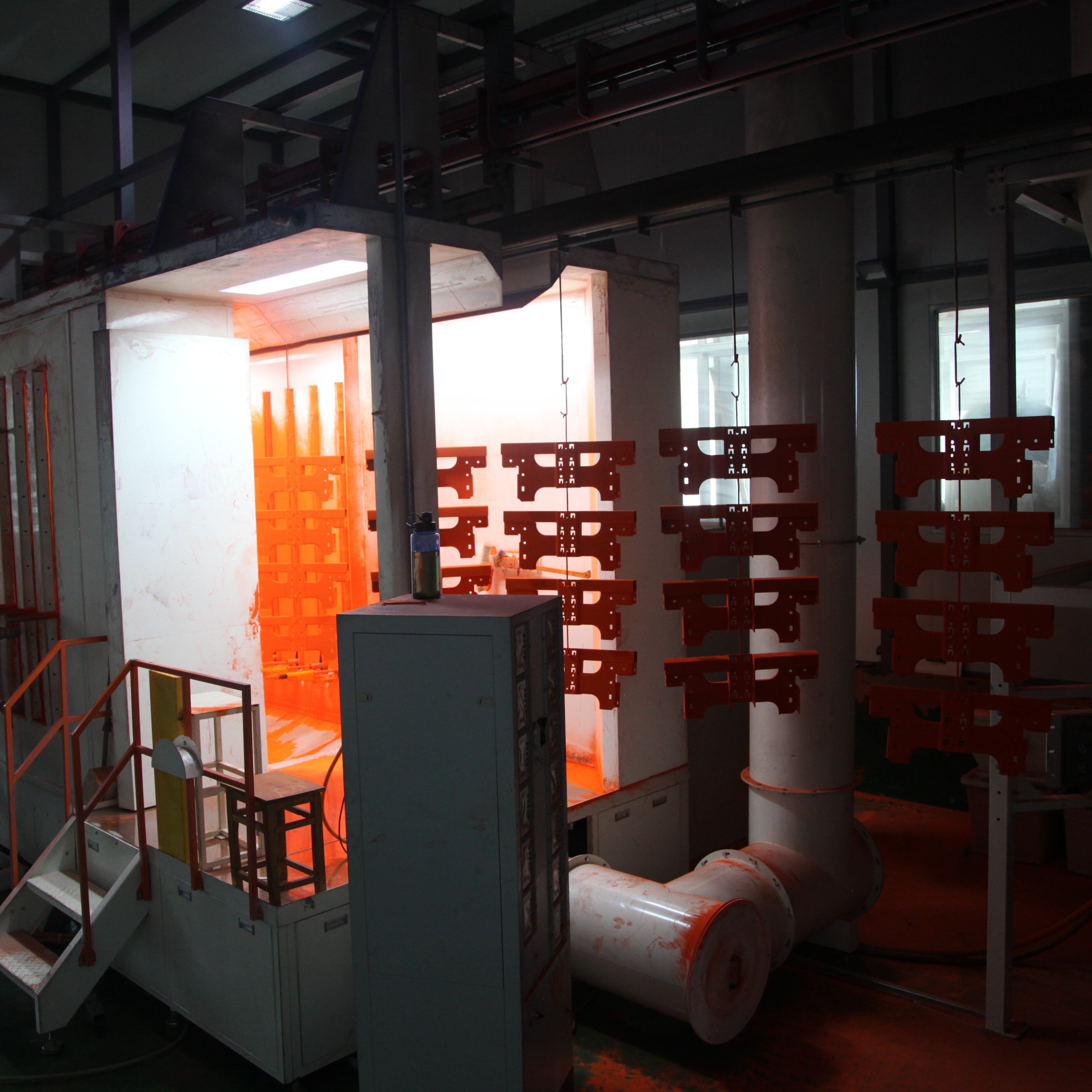
Spray Performance: Nozzle Function, Field Uniformity, and Wrap-Around Coverage
Clogged Nozzles, Inconsistent Powder Flow, and Sputtering in Electrostatic Spray Guns
When nozzles get clogged or when powder flows erratically, it leads to those annoying sputter patterns and inconsistent film builds that can actually raise rejection rates as much as 15% across various industrial operations. Most blockages happen because certain powders attract moisture from the air and then clump together right at the nozzle openings, messing up that important electrostatic charge cloud we rely on for proper coating. Not sticking to regular maintenance schedules or using wrong formulation types just makes things worse over time. Looking at spray angles regularly and checking how evenly the powder is flowing works wonders. Using pattern analysis tools during these checks helps spot problems early. And companies that set up proper cleaning routines for their nozzles see about a 22% drop in wasted materials according to recent industry reports from 2023. Getting air pressure settings right matters too since this directly affects how well the powder disperses and holds onto its charge during application.
Edge Coverage Gaps and Low Wrap Due to Electrostatic Field Distortion
When dealing with electrostatic fields around those tricky sharp corners and deep recesses, we often run into problems with coverage gaps and poor wrap-around performance. The field lines tend to bunch up on the outside surfaces while the inside areas get left behind, which happens because of something called the Faraday cage effect. On complex parts with lots of detail, this can cut down our wrapping efficiency by roughly 30 to 40 percent compared to simple flat panels. To fix these issues, operators need to make several coordinated changes at once. First, reducing the kilovoltage helps get better penetration into those hard-to-reach cavities. Then, shifting the spray tip position by about 5 to 10 degrees from centerline redistributes the field strength more evenly across the part surface. Finally, matching the machine's movement speed with the powder output rate prevents those annoying orange peel textures or thin spots where coating doesn't stick properly.
Coating Quality Defects Rooted in Low Transfer Efficiency
Poor transfer efficiency really messes with coating quality. It's not just about wasting materials either. The whole process gets unstable when too little powder sticks during the first application. Common problems include grounding issues, voltage imbalances, or blocked nozzles. Operators tend to spray extra powder to make up for this, which causes all sorts of problems. Film thickness becomes inconsistent and after curing we see things like runs, sags, or those annoying cracks that look like dried mud. At the same time, areas where adhesion is weak develop thin spots that are prone to corrosion, chipping, and just don't hold up well mechanically. Plants running under 70% transfer efficiency typically face around 40% more defects and rework compared to properly functioning systems. This means longer production cycles, higher energy consumption, and finishes that vary from batch to batch instead of staying consistent throughout manufacturing.
Systematic Troubleshooting and Calibration of Electrostatic Powder Coating Systems
Step-by-Step Diagnostic Workflow: From Observation to Parameter Adjustment
A structured diagnostic workflow resolves 78% of electrostatic powder coating system failures when grounded in empirical observation (Parker Ionics 2023). Begin with visual and physical assessment:
- Isolate symptom patterns: Localized spark marks point to grounding faults; patchy film thickness suggests voltage instability or clogged nozzles.
- Test powder flow consistency using a fluidization test—clogged nozzles can cut transfer efficiency by up to 40%.
- Verify grounding resistance with a multimeter; values exceeding 1 megohm confirm charge dissipation issues (Gema 2022).
Then calibrate key parameters:
- Adjust voltage incrementally across the 30–100 kV range—prioritizing lower settings (e.g., <50 kV) for complex geometries to suppress Faraday cage effects.
- Set gun-to-part distance between 150–300 mm to balance wrap coverage and back ionization control.
- Tune airflow to 0.5–1.5 bar to ensure uniform particle dispersion without turbulence-induced charge loss.
Final validation requires test runs on representative scrap materials. Systems achieving >85% transfer efficiency consistently sustain <5% defect rates in full-scale production.
FAQ
What are common grounding issues in powder coating systems?
Common grounding issues include poor connection between parts and the ground, dirty hooks, or using inadequate thickness of ground wires, leading to uneven powder application and spark marks.
How does back ionization affect powder coating efficiency?
Back ionization occurs when excess charged particles repel new ones, hindering their adhesion, which particularly affects complex geometries, reducing efficiency by 40-60%.
Why is high voltage not always better in electrostatic powder coating?
High voltage above 100 kV can cause back ionization, ozone generation, and dielectric breakdown, and optimal settings depend on material and part design rather than maximizing voltage.
How can nozzle blockages affect spraying performance?
Nozzle blockages can cause inconsistent powder flow, resulting in sputtering and rejection rate increase by up to 15%, mainly due to moisture-related clumping in certain powders.
What is the impact of poor transfer efficiency on coating quality?
Poor transfer efficiency leads to inconsistent film thickness, weak adhesion, and defects like runs and sags, with affected processes often facing up to 40% more defects.
Table of Contents
- Electrical Integrity: Grounding, Charge Stability, and Voltage Optimization
- Spray Performance: Nozzle Function, Field Uniformity, and Wrap-Around Coverage
- Coating Quality Defects Rooted in Low Transfer Efficiency
- Systematic Troubleshooting and Calibration of Electrostatic Powder Coating Systems
-
FAQ
- What are common grounding issues in powder coating systems?
- How does back ionization affect powder coating efficiency?
- Why is high voltage not always better in electrostatic powder coating?
- How can nozzle blockages affect spraying performance?
- What is the impact of poor transfer efficiency on coating quality?